
Baihui Cryogenic Equipment
Huzhou Baihui Cryogenic Equipment Co., Ltd
Huzhou Baihui Cryogenic Equipment Co., Ltd

Provide you with the latest enterprise and industry news
A cryogenic pump does not operate independently from its piping. During cooldown, startup and normal operation, the suction and discharge lines continually transmit temperature changes, liquid weight, vibration and pressure forces.
If these loads are not properly controlled, the pipework can impose excessive force or bending moment on the pump connections. The result may be recurring leakage, damaged fittings, disturbed alignment or shortened equipment life—even when the pump itself was correctly selected.
Reliable installation therefore requires more than securely fixing every pipe. The system must be supported while still allowing controlled movement.
Before startup, much of the pump and piping may be close to ambient temperature. When cryogenic liquid enters the system, the metal temperature falls rapidly and the pipe becomes shorter.
The total contraction depends on several factors:
For reciprocating pump installations handling oxygen, nitrogen or argon, EIGA notes that suction-pipe length can decrease by approximately 3 mm per metre during cooldown where no other thermal-contraction provision is present. This is an illustrative industry value, not a universal design allowance; the actual movement should be calculated for the selected material and operating temperature. eiga.eu
Even a relatively short line can therefore generate significant stress if both ends are rigidly restrained.
A pump connection is intended to convey liquid, not to function as a support for poorly aligned pipework.
EIGA guidance identifies several loads that should be isolated from a cryogenic pump housing:
Suitable pipe flexibility and properly located supports can prevent these forces from being transferred directly to the pump. The pump manufacturer should also specify acceptable external loads and moments at the suction and discharge connections. eiga.eu
During installation, the pipe should meet the pump connection in its natural position. Bolts, clamps or a flexible hose should not be used to pull misaligned components together. A connection that appears acceptable at ambient temperature may impose a much larger load after cooldown.
Cryogenic piping needs support, but not every support should rigidly lock the pipe in every direction.
A properly engineered support arrangement can use different components for different functions:
The appropriate arrangement depends on the pipe length, material, temperature, routing and allowable nozzle loads. Arbitrary support spacing or an improvised flexible section should not replace a piping-stress review.
Chart’s installation guidance for vacuum-insulated piping similarly warns that cryogenic contraction must be accommodated. Its examples use rollers or designed flexible sections to allow axial movement and caution against overtightening clamps where the piping needs to move. files.chartindustries.com
Braided metal hose is commonly installed near a cryogenic pump to help isolate vibration and manage limited thermal movement. However, it is not a universal correction for poor pipe routing.
A flexible connection should not be:
For some reciprocating-pump installations, EIGA recommends installing a suction-side flexible hose slightly compressed where it is specifically intended to accommodate the shortening of the suction line during cooldown. The required condition must still be confirmed with the hose and pump manufacturers. eiga.eu
A flexible hose should be treated as an engineered pressure component, not as a convenient way to correct fabrication errors.
Thermal contraction is not the only source of movement. A reciprocating cryogenic pump produces pulsating flow as its piston or plunger accelerates and decelerates.
These pressure and flow fluctuations can contribute to:
Pulsation dampeners may be used where required, but their selection and position should be based on the pump and system design. They do not compensate for inadequate pipe support or poor alignment.
Supports should control harmful vibration without creating rigid constraints that prevent thermal movement. Achieving both objectives is one reason cryogenic pump piping should be assessed as a complete system.
The suction line affects both mechanical loading and hydraulic performance.
It should generally be short and direct, with unnecessary bends and restrictions avoided. Proper insulation reduces heat entering the liquid, while suitable routing helps prevent gas from becoming trapped at high points. Adequate net positive suction head must be maintained throughout the expected tank-level range to reduce the risk of vapor formation and cavitation. eiga.eu
A mechanically flexible suction arrangement is therefore not enough on its own. The design must also control:
Changing pipe diameter, adding a filter or modifying the tank-to-pump route can affect both the available suction conditions and the loads applied to the pump.
Many installation problems become visible during temperature changes rather than during steady operation.
As the system cools, different sections may contract at different rates. During shutdown and warm-up, the direction of movement reverses. Repeated cycles can gradually loosen a marginal connection or move a poorly restrained pipe out of alignment.
During initial commissioning and after piping modifications, personnel should observe the system from a safe location and check for:
The system should be depressurized and made safe before adjustments are attempted. A cold or pressurized pipe should not be forced back into position.
Replacing a pump with a different model, moving a valve or adding a filter can change the mechanical behavior of the system.
A modification review should confirm:
Adding more clamps is not automatically the correct solution to visible pipe movement. A new rigid restraint can transfer the load to a weaker fitting or directly into the pump housing.
Reliable cryogenic transfer depends on the interaction between the pump, tank, piping, supports, flexible connections, valves and operating procedure.
The piping should be strong enough to carry the required pressure and weight, flexible enough to accommodate calculated thermal movement and supported so that excessive loads do not reach the pump.
There is no single support arrangement or flexible-hose length that is correct for every installation. Final design should be based on the actual cryogenic liquid, temperature range, pipe material, equipment layout, operating cycle and pump-manufacturer requirements.
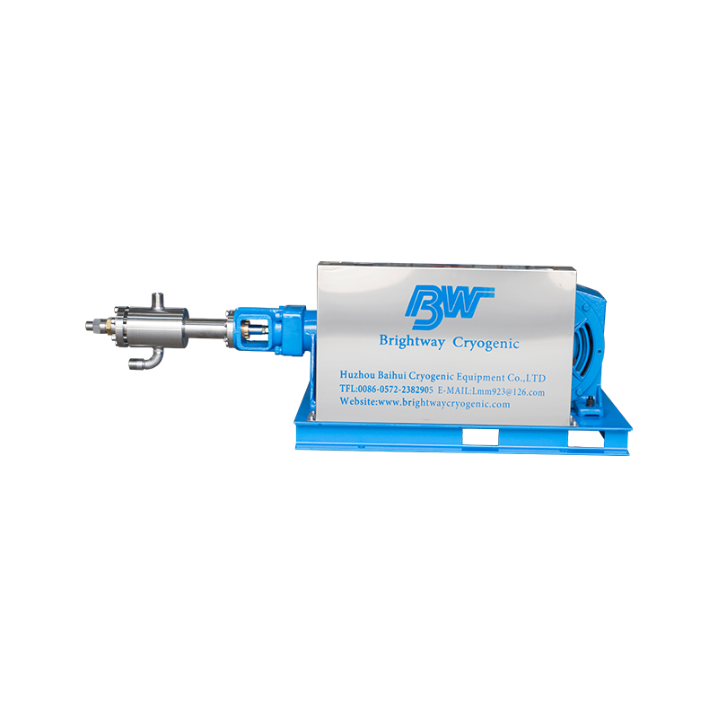
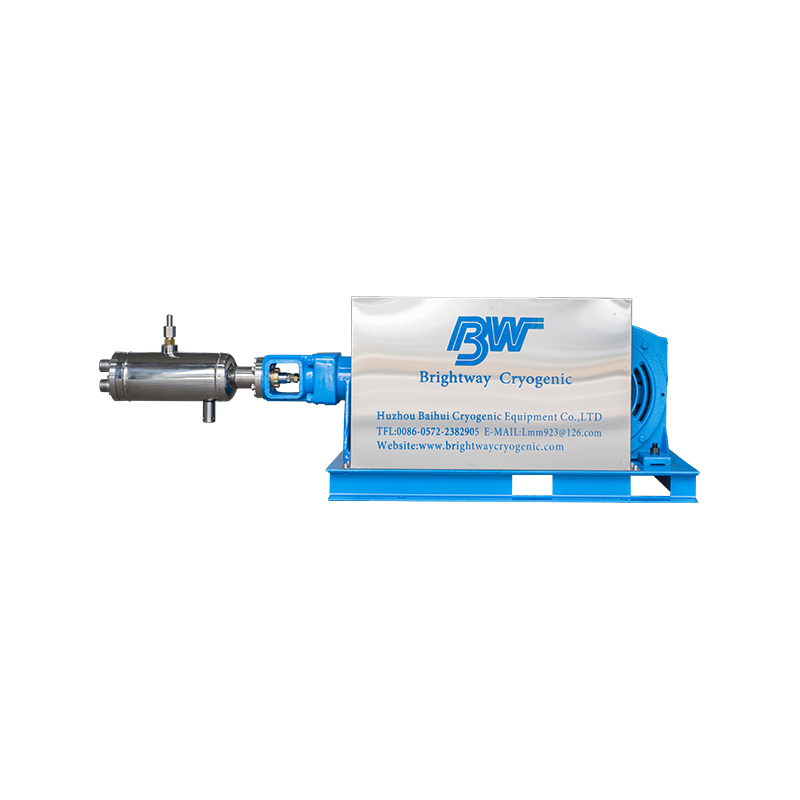
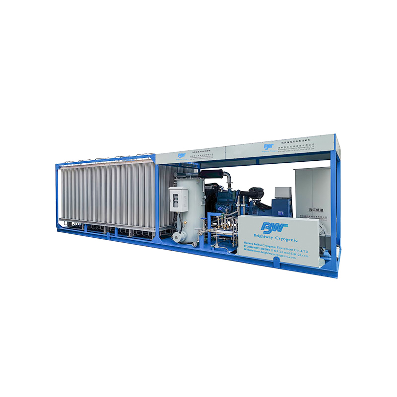
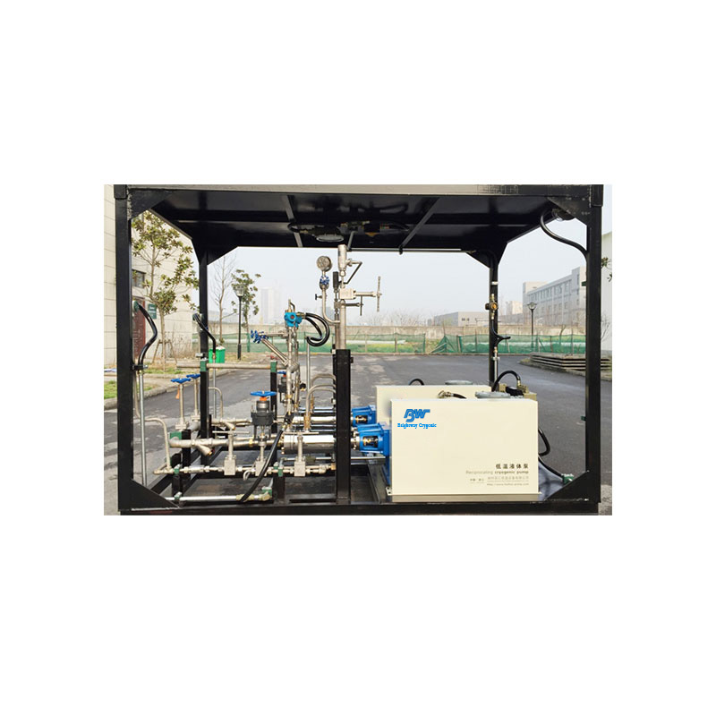
Brightway Cryogenic supplies cryogenic pumps and integrated equipment for industrial-gas applications. Pump-skid and piping configurations should be confirmed according to the project’s actual operating conditions and installation environment.
 Add: Building A38, China Energy Conservation and Environmental Protection Industrial Park, No. 1506, Yishan Road, Wuxing District, Huzhou City, Zhejiang Province, China
 Phone: +86-13757082585
Telphone: +86-572-2382905
 E-Mail: [email protected]
Copyright © Huzhou Baihui Cryogenic Equipment Co.,Ltd All Rights Reserved.

 English
 русский
 Español